Yazar arşivleri: Oguzhan Eren

Dual 5Ghz Performance Test with Aruba AP345

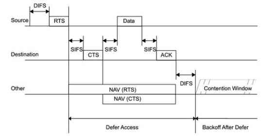
Many people, who know how “WiFi contention mechanism” works, ask that it is really viable to have two same-band radios in the same AP box.

So, you can run one 2.4Ghz and one 5Ghz radio in a single AP box but can you run two 5Ghz radios at the same time.

Here, “at the same” does not mean simultaneous Tx or Rx. One should Tx while the other is receiving. So, basically, they should “interfere” with each other because the Tx and Rx are so close, right? Even if they choose UNI-1 and UNI-2 Ext bands and try to move away from each other in the spectrum view, they should see the interference due to close proximity.

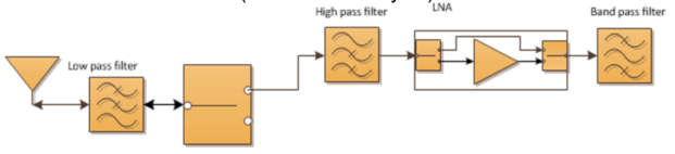
Theoretically, this can be solved via a physical – hardware based filter (band pass filter).

When there is a filter for a radio, that radio only hears what filter “filters” :) The rest is dropped.

So, let’s test if Aruba AP345 dual 5Ghz mode works as expected:

Here we have two SSIDs:

spectrum-1

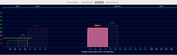
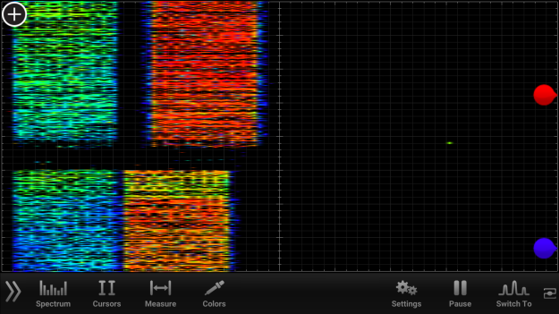
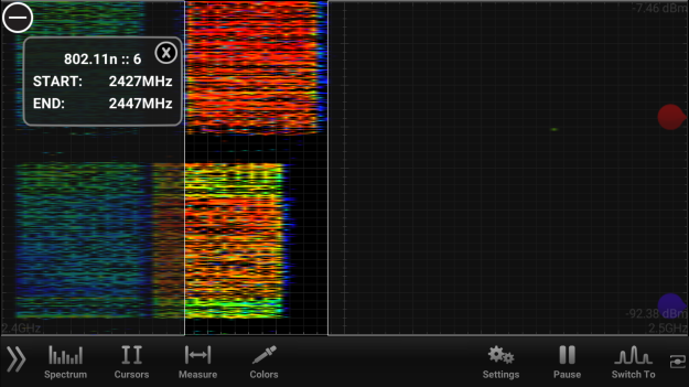
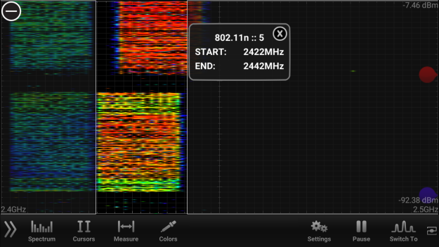
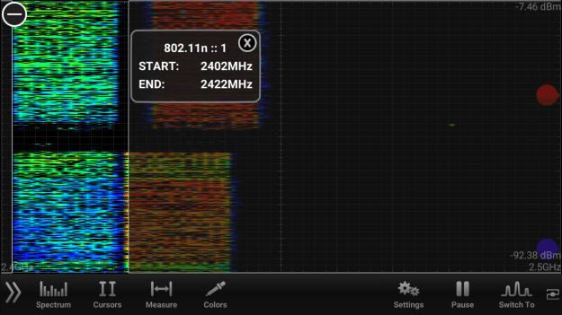
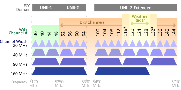
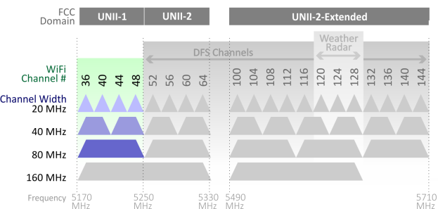
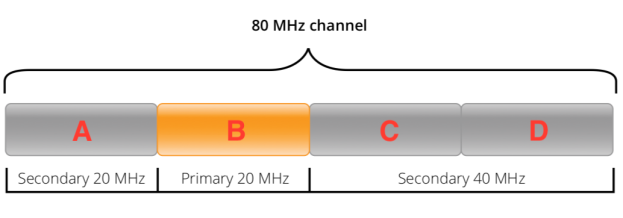
First SSID is 5Ghz1 and it is being broadcast on ch60E (80Mhz wide and it is on UNI2) and the other SSID is again named as 5Ghz1 but on ch104E (80Mhz and UNI2-Ext).

They are being broadcast via a single Aruba AP345. So, both radios on the AP are on 5Ghz, meaning no 2.4Ghz SSID on that AP.

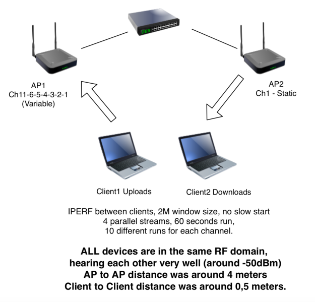
Test Case 1 – Client1 Tx, Client2 Rx (iperf between clients) when they’re connected to the SAME 5Ghz radio.

If we connect two 2×2 11ac clients to the same radio, of course they will share the medium, right?

So, here are the results:

test-1-same-radio

In this case, client one is connected to the 80Mhz SSID with max rate (867Mbps), the other is the same (867Mbps)

..and Client1 is sending traffic to Client2, so basically, they are sharing the air and they are getting around “half” of the total air bandwidth (we can say that 2-stream air bandwidth is around 600Mbps)

So, with air sharing, we’re processing around 300Mbps from each client.

What if we connect one client to radio1-5Ghz and the other client to radio2-5Ghz?

Test Case 2 – Client1 Tx, Client2 Rx (iperf between clients) when they’re connected to the different 5Ghz radios in the same AP.

If those radios are in the same box (very close proximity to each other), they should interfere with each other, so we should be able to get the results similar to test case 1 above, right?

Let’s test this:

test-2-diff-radios-

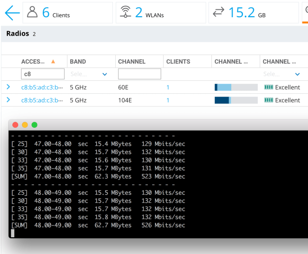
In this test, clients are connected to different radios. Client1 is sending traffic to Client2. So, one radio is shouting at max, while the other is trying to listen.

So, they should interfere and we should see the below adverse effects, right?

1- The performance on the radios should be lower than expected due to excessive noise, so, bad client SNRs. So, low throughput numbers.

2- Transmitting radio is very close the receiving radio, so receiving radio should defer a lot, because of signal (or even energy) detect threshold(s), so receiving radio should suffer a lot.

So, we should see really low throughput numbers due to these effects, so, in the end, that should equal to (or maybe a bit better than) the case number 1 above (connecting to the same radio)

However, in reality, we’re not seeing the adverse effects explained above.

Transmitting radio is sending ~520Mbps data, while the other radio is receiving the same, without affecting each other too much.

So, that means that dual 5Ghz feature on Aruba AP345 just works. That means there is a very strong hardware based filtering between 5Ghz radios and those radios do not interfere with each other even while one radio doing Tx, while the other is doing Rx.

This is very rough test. No RF-cage, no special config tuning or so. I’ve seen that people are talking about Dual-5Ghz, so I grabbed an AP345 and did the test between my computer and my phone. AOS 8.4.0.1.

Summary

Aruba AP345 has the correct level of filtering between 5Ghz radios. When one WiFi client is sending data to another WiFi client (one radio Tx, the other radio Rx scenario), here are the results:

If the clients are connected to the same radio, throughput between clients: ~280Mbps

If the clients are connected to the different 5Ghz radios in the same AP, throughput between clients: ~520Mbps.


Measuring the Effects of WiFi Low Rate Transmissions on the High Rate WiFi Traffic in the Same Frequency

“It is very likely that a communication from a client which has 867Mbps rate could easily be “intercepted” or “lowered” by another client which is transmitting 6Mbps on the very same channel that the high-rate client operates. So, in this case, the high rate client or the AP will be affected by this low rate client, but the question is how much?”

Here are the details: Measuring the Effects of WiFi Low Rate Transmissions on the High Rate WiFi Traffic in the Same Frequency – updated Oct 2018


Oguzhan EREN, CWNE#266

4 Channel Plan with OFDM. An ACI Analysis.

Here we have a “Saturday Night Test!”

We were talking about 4 channel plan with OFDM modulation in 2,4Ghz band and trying to understand whether that is a reality or not.

We all know that the non-overlapping channels in 2,4Ghz band are 1,6 and 11; right?

However, if the numbering is consistent and correct between 2,4Ghz and 5Ghz, there are 4 channel-numbers between non-overlapping 5G channels but why is there 5 channel-numbers between non-overlapping 2,4Ghz channels?

For example, you have channel 36 and plus 4, you have channel 40 and this is non-overlapping with each other. So, if that is OFDM and we also have OFDM in 2,4Ghz; then the same should apply right?

So, if we have ch1 and plus4, the channel 5 should NOT overlap with the channel 1, if we use the exact the same channel spacing math between 2,4Ghz and 5Ghz.

So, what is the reality here?

Channel 1 and Channel 5 (like ch36 and ch40). Are they non-overlapping or no?

Let’s test this.

We should be careful, because there should not be any DSSS transmissions there (due to 11b client Tx or due to RTS/CTS to “protect” them because DSSS ruins this test as this is 22Mhz wide, not 20Mhz wide like OFDM Tx)

So, to be sure about zero DSSS Tx around, I removed all DSSS rates and started with 12Mbps as the basic rate, Tx rate and beacon rate. Yes there could be DSSS Tx in the area that I run these tests but I checked the air and saw that no STA around was doing DSSS.

So, here is my ultra basic test setup:

One client downloads from an AP, another client downloads from another AP, all are in the same RF domain, meaning they do hear each other very well.

So, in this case, if AP1 and AP2 both are on the same channel, that is called CCI, right? So, they share the air.

If they are on ch1 and ch11, that means they don’t contend for the medium, so they can use their “own” air bandwidth, right?

If they are on ch1 and ch6, and if they are placed apart from each other (o couple of meters) they won’t need to go into contention again, so they can again use their own air, right? –because ch1 and ch6 do not overlap, we all know this very well.

What if ch1 and ch5? With a couple of meters away from each other, will they contend for the medium?

Let’s test this with pure OFDM Tx.


Screen Shot 2018-07-15 at 15.30.41


With the above test scenario, I run these tests

  • iPerf between clients, AP1 is on ch11, AP2 is on ch1
  • iPerf between clients, AP1 is on ch6, AP2 is on ch1
  • iPerf between clients, AP1 is on ch5, AP2 is on ch1
  • iPerf between clients, AP1 is on ch4, AP2 is on ch1
  • iPerf between clients, AP1 is on ch3, AP2 is on ch1
  • iPerf between clients, AP1 is on ch2, AP2 is on ch1
  • iPerf between clients, AP1 is on ch1, AP2 is on ch1

(Clients were 2×2 11ac clients, connected to the 2,4Ghz 11n radios, 20Mhz channel, with MCS15, 144Mbps rate, SGI, 64 QAM 5/6)

Here are the results:

Screen Shot 2018-07-15 at 15.51.07

So, we can clearly see that the non-overlapping channels give the best overall throughput between clients.

For example, if the AP1 is on Ch11 and the AP2 is on Ch1, then the average throughput between clients are (completely non-controlled environment, with lots of interfering APs and Clients around) 85,64Mbps.

When we see the result between clients, when the AP1 is on Ch6 and AP2 is on Ch1, that’s another non-overlapping scenario. The result is 78,96Mbps between clients.

However, we can clearly see that, Ch5 and Ch1 does also NOT overlap with the results similar to the other scenarios, like 11-1 and 6-1.

Let’s get closer to the AP2 Ch1. When we configure AP1 in Ch4, things start to get bad with around %50 throughput loss, due to contention between APs.

That’s why Ch4-Ch1 contention drops the performance to 41Mbps and it stays the same even with Ch1-Ch1 CCI contention, in which the performance is around 42Mbps.

Here is the spectrum output while the tests were running:

spectrum1

The above part is the ch6 – ch1 test, and the below is where ch6 stays:

ch6

So, the channel 6 with OFDM modulation is there, starts with 2427Mhz and ends with 2447Mhz.

..but where is channel 5? Here it is:

ch5

Channel 5 starts with 2422Mhz. Does it interfere with channel 1. Where does channel 1 ends? Any overlap. No, they don’t overlap with OFDM, as you can see from the above waterfall output.

Here is the channel 1 and it ends at the exact point that ch5 starts, like 5Ghz OFDM channels.

ch1

So, ch1 ends at 2422Mhz and ch5 starts at 2422Mhz, so they DON’T overlap and we can prove this via simple throughput runs between clients with ch1-ch6 pairs vs ch1-ch5 pairs.


What are the “DFS” Channels and how are they dealing with RADAR systems?

5Ghz band is huge spectrum. However, there is a one big issue with this channel plan: DFS Channels.

DFS stands for “Dynamic Frequency Selection” and if your want to use some channels in the 5Ghz band, you should obey DFS rules.

DFS channels are used by some military and civilian RADAR systems and WiFi should be shut itself off, immediately after it detects the presence of RADAR pulses. So, if an AP has no RADAR detection capabilities, cannot operate in DFS channels.

Why are we dealing with this? Are there any non-DFS frequencies? Yes, there are.

For example, the below chart shows the band plan (5Ghz, ETSI) including DFS channels.

graphic-80211-acChannels-all


Let’s remove the DFS channels, and make them grey-out:


graphic-80211-acChannels-noDFS


Oh! We lost nearly all our space, right? We only have some indoor channels with limited power levels, no outdoor channels and very limited spectrum to use (only 80Mhz total)

So, this non-DFS area tells us that we MUST use DFS channels and we need to understand DFS rules.

What are the DFS rules? Where are they written?

For ETSI regulatory domain that I’m working in, these details are writting in the document called “ETSI EN 301 893 v1.8.1 (2015-03)” document. (I’m not sure if there are updated version of this doc)

Link to the original document:  http://www.etsi.org/deliver/etsi_en/301800_301899/301893/01.08.01_60/en_301893v010801p.pdf

According to this document, the section 4.7 states the details about the DFS operation, such as:

  • There should be “channel availability check” before attempting the first transmission on the channel. CAC is 60 seconds but 10 minutes (for frequencies between 5600-5650Mhz). So, APs should wait first, then if there is no RADAR transmission heard on the channel for at least 60 seconds or 10 minutes, then start transmitting.
  • The device may conduct off-channel scanning to understand the presence of RADAR signals, these off-channel scannings should last minimum 6 minutes or 1 hour for frequencies between 5600-5650Mhz.
  • If RADAR is seen in a channel, no more Tx there, in the next 30 minutes.
  • If RADAR is seen in a channel, the channel should be emptied in max 10 seconds.
  • During these 10 second channel move time, total Tx duration should not last more than 1 seconds.

Screen Shot 2017-12-07 at 18.21.52

If every WLAN device obeys these rules, then RADAR operators will be happy, but why?

Here is a civilian weather radar output for Istanbul, Turkey. This is to see rain, snow etc. Meteorological Institutions are using these RADARs to detect atmospheric events in an area. So, for the below image, we can see some rain in the south of Istanbul and some other areas as well. This is a regular output for a rainy day(s):

ist-weather-radar

However, what about the below image for Ankara?

ankara-weather-radar

What are those straight lines nearly around the top right of the image. Clouds with rain? Looks unnatural, right?

These are some WiFi signals captured by Ankara RADAR, probably coming from in the middle of the city. RADARs are using very very high gain antennas and they can pick up your very weak WiFi transmission. So, your WiFi transmission, if you do not obey DFS rules, literally blinds the RADAR and it cannot see the atmosphere, it cannot work as expected.

This is the critical point about DFS and we should all know DFS and its rules, to be careful about that.


What is “Cellular Coexistence” and “Filtering” for 802.11 Networks?

When we are running enterprise or telco grade 802.11 networks in an high density indoor area, probably there are also some 3G or LTE indoor antennas broadcasting 3G or LTE signal in that area, alongside with the WLAN coverage.

However, there are two types of “disturbance” coming from nearby LTE radios to the WLAN devices.

  • Disturbance from high level of RF energy hitting to the radio, so “desensing” it.
  • Disturbance from a side products of the signals combined at the Rx

Let’s start from the first one. If the WLAN device’s Rx side is hit by high energy coming from a nearby LTE radio, the powerful signal can “desensitize” it, causing its AGC circuit to make the device less sensitive to the regular WLAN communication. So, that means low performance for WLAN.

When can this happen? What is the dangerous space between the high-power indoor/outdoor LTE e-node B and WLAN device? This “separation” should be more than 30-40 meters, if the WLAN Rx is not filtered correctly.

If, somehow, the amplitude of the LTE signal hits to WLAN equipment at -45 dbm or higher; the radio starts to suffer and shows some performance degregation, if used heavily.

If the incoming signal is around -15 dbm at the WLAN Rx, then the radio is completely blocked, no Tx or Rx is possible. It is interesting that the incoming signal’s frequency is NOT important here, the “desensitization” is happening because of the power, not because of the frequency.

So, the AP vendor should be using correct filters to block this high energy RF, BEFORE it hits to the AGC circuit. So, if you are using “filtered” AP, nearby high-power LTE transmitters won’t be able to degrage your performance, even if they are located as close as 1 meter. So, for this “high power nearby LTE transmitters” issue, the APs should be selected as “filtered” models, if there are strong LTE signals around. If there are only 802.11 signals around, like regular home WiFi or low-usage WiFi setup, non-filtered APs can also be used.

Screen Shot 2017-12-07 at 16.11.26

This above diagram is a basic representation of the radio, with correct filters in-place.

Let’s move onto the next “disturbance”. Side products or harmonics.

This is another effect that a WLAN Rx can receive from the nearby 3G/LTE stations.

For example, think about a 3G transmitter, which transmits ~1800Mhz (this is, lower frequency, hence F1 here) and ~2100Mhz (this is F2) at the same time. So, they produce harmonics and we can find this with 2xF2-F1 formula, which is (2 x 2100) – 1800 = 2400Mhz (Bingo!)

So, this is common problem for 3G operators using those frequencies together withing the same Tx chains.

This harmonics interference can be detected with an external spectrum analyzer:

interference seen with external spectrum analyser

Also, if the APs are spectrum analysis capable, they can also see this interference:

interference seen by aruba ap

Swept spectrogram output of this harmonics is like below:

cellular interferenc hit

So, these interference does mainly affect 2.4Ghz band and less likely has an effect on 5Ghz band.

To mitigate these types of effects, mainly “high-power nearby signal” effect, it is better to use “filtered” APs at required locations.

80Mhz Channels in 802.11ac and the “Backward Compatibility”

With the introduction of 802.11ac, we met 80Mhz channels. It meant more data because more spectrum is utilized when a packet is being transmitted.

Of course, there are other consequences when using 80Mhz channels, such as being more prone to interference, less channels to use etc. However, what about the backward compatibility?

We know that still some devices out there using 20Mhz channels in 5Ghz band. Yes, these are legacy 802.11a devices. And also there are 40Mhz devices. And now we have 80Mhz client devices.

What will happen when there are three types of devices (20Mhz, 40Mhz and 80Mhz) connected to an AP which supports 80Mhz? How is backward compatibility working here?

Another question is about Co-Channel Interference. What will happen if there are two 80Mhz APs sharing the same 80Mhz portion of the spectrum? How are they handle the CCI issue?

So, the backward compatibility is solved nicely with 80Mhz channels. Every 80Mhz channel consists of sub 40 and 20Mhz channels.

Screen Shot 2017-12-07 at 12.12.25

For the example, the above image represents an 80Mhz channel. It consists of 4 blocks and each block is 20Mhz.

For example, let’s look at the lower portion of the spectrum in the 5Ghz band, which is UNII-1 band.

UNII-1 is clean from DFS and sometimes we are hit badly by weather RADARs, so sometimes it is better to stay on UNII-1. What is DFS and how is it being affected by RADARs? These could be the subjects of another blog post.

So, when we put 2 80Mhz APs in the same band, say, UNII-1, which has 4 x 20Mhz channels which are 36, 40, 44 and 48; two APs will cover the same spectrum in the entire UNII-1 band. Two APs will be broadcasting on 36+40+44+48.

However, automatically (based on the gear you are using), APs will select different 20Mhz and 40Mhz sub-portions despite their same 80Mhz channel.

Let’s look at the below image, again:

Screen Shot 2017-12-07 at 12.12.25

Assume that A is channel 36. B is channel 40. C is channel 44 and D is channel 48.

Your first 80Mhz AP is on A+B+C+D

And, your second 80Mhz is AP is also on the same band: A+B+C+D

However, according to your radio management mechanism that you use on your APs, they will be selecting different “sub”channels for the 40Mhz and 20Mhz operation.

For example, if you are a 20Mhz client, which sub-channel you’ll use on the first AP? Which sub-channel be used by the second AP? Of course, they will be selecting different channels for 20Mhz operation even though they are on the same 80Mhz channel. At the same time, they will be selecting different 40Mhz sub-channels.. However, the selected 40Mhz sub-portion, should include the 20Mhz subportion.

For example, the first AP is on A+B+C+D as 80Mhz channels.

“A” can be the 20Mhz channel. This will be used for beaconing, NAV, mgmt frames, 802.11a frames, all 20Mhz supported clients’ frames etc.

A+B can be the 40Mhz channel. This will be used for the 40Mhz clients. The 40Mhz portion should include the “A” here. So it must be A+B. For example, B+C portion cannot be used as the 40Mhz sub-portion. C+D cannot be the 40Mhz portion for this AP, as well.

On the other hand, the second AP will be selecting different 20Mhz (hence, 40Mhz) subportion.

For example, AP1 is on

  • A+B+C+D as 80Mhz.
  • A+B as 40Mhz.
  • A as 20Mhz.

AP2 will select like:

  • A+B+C+D as 80Mhz.
  • C+D as 40Mhz.
  • C as 20Mhz.

So, this will decrease the CCI within the ABCD (80Mhz) block and this will also provide simultaneous transmissions to different 20Mhz or 40Mhz channels by different APs. For example, given the channels selected above, AP1 will be communicating with a 20Mhz client on channel A, and at the same time, AP2 will be able to communicate another 20Mhz client on channel C.

So, 80Mhz channels also provides backward compatibility for older 20 or 40Mhz clients and, at the same time, the radio resource allocation mechanism are assigning different sub-channels to different APs, to utilize the air better.

What is “Hidden Node Problem” and why is it a critical thing for 802.11 networks?

When designing WiFi networks, everybody thinks about the “coverage” first.

Are you covering correctly? Yes. Then it is OK. If you need more data, more capacity, more speed; just add more APs.

It seems simple, but is is not so simple in the real world.

Also, I’m hearing such statements that “Our hall-placed APs were good at first but when many clients from different rooms connect to the same AP at the same time, the WiFi performance suffers”

Why is this the case? What is the missing point here?

It is “hidden node problem” and it is one of the highly under-estimated problems in the entire WiFi world today.

According to the simple rule of CSMA/CA mechanism used in 802.11, all stations should be able to hear each other. This is the rule.

hidden-node


Think about the station B is the Access Point, in the above diagram.

Station A can transmit data to the AP (station B) and the AP can transmit data to the station A.

On the other hand. Station C can transmit data to AP, and the AP can transmit data to the station C.

All seems correct, right? A can hear the AP, C can hear the AP; that means AP can cover the stations, so there shouldn’t be any problem.

However, we have a big problem here. The stations A and C, cannot hear each other. In other words, their transmissions cannot reach each other. So that’s a problem and this is called “Hidden Node Problem” because in our diagram, Client A and Client C are “hidden” from each other.

Why is this a problem?

CSMA/CA works like (simply) “if somebody is not transmitting, wait and still no one is transmitting, then you can transmit”.  So, it relies on Tx station’s own Rx to see if somebody is Txing or not. What if somebody is actually transmitting but the station cannot hear that? Of course it will transmit and it will cause a collision.

Collision means re-transmit, and re-transmit means lower speed transmission, and lower speed transmission means longer “duration” values for everybody out there as longer NAVs for all STAs, which means more waiting in the medium by everyone, which means less overall throughput from the air.

So, in short, in our WiFi cell design, all STAs should be able to hear each other to make WiFi work correctly and efficiently.

On the other hand, RTS/CTS mechanism could be utilized in hidden-node environments, in which, AP uses RTS and CTS frames to distribute NAV timers in the RF domain to inform STAs to wait for duration specified in the CTS frame.

35640-RTS-CTS_Handshake

As shown in the above diagram, RTS packet from the source is also used to distribute NAV timer to other and the CTS is also distributing another NAV timer which means everybody out there (either received RTS or CTS) will be waiting until NAV timer expires plus DIFS and then they will all go into contention window)

Of course there is a possibility that many clients try to send RTS at the same exact time. This is possible. However, in general, RTS CTS mechanism makes good job relieving hidden node issues.

As you can see from the above explanations, all WiFi channel access mechanism is based on the assumption that every STA hears all transmission in the RF domain. However, in the real world, unfortunately, many WiFi designs are based on “coverage” rather than “capacity” which means very large coverage areas which makes clients cannot hear each other, lowering overall performance of the cell.

Do we need Spectrum Analysis Capable APs to see non-WiFi Energy?

Many WiFi-focused people have seen some disruptive non-WiFi interference on WiFi bands. Those can be on 2.4Ghz and 5Ghz but the 2.4Ghz is especially crowded in terms of both WiFi and non-WiFi energy levels on those bands.

Enterprise and Telco grade access points should be able to detect/understand and measure the energy levels, not only coming from WiFi based sources, but also non-WiFi based sources.

There can be numerous non-WiFi energy sources hitting to 2.4Ghz band, such as:

  • Non-data-transmitting devices, such as Microwave ovens or other magnetron based devices.
  • Data transmitting, in-band non-WiFi devices, such as video bridges.
  • Data transmitting, out-of-band non-WiFi devices, such as LTE or 3G multi-band equipment, whose -probably- third harmonics hit 2.4Ghz WiFi band.

On the other hands, there are basically two types of Access Points, in the enterprise/telco market.

  • Spectrum Capable Aps, which have integrated spectrum analyzer to see the raw energy in the environment.
  • Non-spectrum capable Aps, which have no spectrum visibility for non-WiFi energy.

However, there is some confusion here. What are the capability levels that we can expect from APs?

  • Capability Level1 – An AP which is doing basic WiFi stuff, but no capability to see non-WiFi energy on the channel. If the Ap is on channel1 and there is a non-WiFi energy on the same frequency, AP cannot see that energy, cannot report it, cannot change channels to jump to a “cleaner” channel.
  • Capability Level2 – An AP which broadcast WiFi signal and sees the channel metrics including WiFi and non-WiFi energy levels on the channel it operates. If there is a non-WiFi energy on the channel, AP can see the existence of non-WiFi energy, can report the level the signal occupies in the given channel/spectrum space and the AP is capable of changing the channel to get better channel with less non-WiFi interference.
  • Capability Level3 – An AP which broadcast WiFi signal and it has correct hardware/software components to see the actual FFT from the channel and it has correct algorithm to see duty cycle of the channel to understand (or tries to understand) the source of the signal whether it is coming from a microwave oven, or from a Bluetooth device or from a Video bridge etc. So, this type of APs can report the “reason” and “source” of the non-WiFi energy.

Some vendors are offering spectrum capable APs, which are on “Capability Level3” and offering non-spectrum capable APs which are on “Capability Level1”

On the other hand, some vendors are offer spectrum capable APs which are Level3 but offering non-spectrum capable APs, interestingly, which are on “Level2”

Now, let’s look at Aruba’s AP207 which does NOT support spectrum analysis capability and it is an entry-level AP.

We know that AP207 has no Level3, and we’ll try to test if AP207 has Capability Level1 or Level2.

For this testing, I used a non-WiFi signal generator from a brand called “Next” which is actually a video transmitter device works on 2.4Ghz band, without obeying any 802.11 transmission rules. No IFS, no contention window, no CSMA/CA, no back-off, no EDT, no NAV. This device just shouts out, without caring about anybody in the band.

next-interferer

I wanted to test Aruba AP207 for this. My aim was to understand which level it is on, in terms of spectrum visibility.

Screen Shot 2017-12-06 at 21.52.10

First test is to define the baseline.

Here is the empty channel values from a 3rd party spectrum analyzer. Video bridge is not working and all 2.4Ghz spectrum seems OK.

interference-no

Aruba AP207 broadcasts a test SSID, with regular load on the channel, and 207 reports that the below channel metrics:

channel-normal

Here, the AP207 reports the following values:

  • %85 of the channel (in this instance, this is channel1) is free.
  • Remaining %15 of the channel is used according to the below values:
  • %2 of the channel is busy, because of this APs “transmitting” frames.
  • %1 of the channel is consumed by non-WiFi or “cannot-be-decoded-WiFi” signals.
  • %12 of the channel is consumed by this APs “receiving” frames. Actually, in this sampling interval, 14559 frame just have hit to the radio Rx, and 14366 of 14559 is actually destined for another WiFi STA in the same channel but also hit to this APs Rx. 193 frames out of 14559 destined for this AP and hit to this AP’s Rx.

Now, it is time to enable video bridge to block all the transmissions on channel 1.

interference-yes

As you can see from the photo above, video device is shouting like crazy in the channel 1..

Now, it is impossible to Tx any 802.11 frame on channel 1 because the WiFi STA tries to Tx but hits energy detect threshold (which is -62dbm), defers access and reports that the channel is busy. Because all of the trials are not successful and the transmitter cannot send even one 802.11 packet, it reports high channel utilization with all of them comes from a non-wifi source, which means the Rx cannot decode the incoming energy, so it is reported as non-WiFi. Sometimes, some distant WiFi transmissions which cannot be decoded at the Rx, can be reported as non-WiFi energy.

So, here are the channel metrics after the interferer device has been turned on:

channel-interfere

As we can see from the above output, the Rx of the AP cannot receive any frame because of the high level of non-WiFi interference seen on the channel.

So, it reports zero Tx and zero Rx and high level of interference. So it can see the non-WiFi interference. It also reports high level of noise.

After a couple of seconds or minutes, the AP selects another channel and jumps to Channel 6, to broadcast its SSID in a fairly clean environment. So, the AP saw the non-WiFi interference and changed the channel to recover from that interference.

arm-channel-change

So, even though AP207 has no spectrum analysis capability, it saw the non-WiFi interference and managed to change the channel to recover itself. The “Reason: N” means that the AP has changed the channel because of “Noise Threshold Exceeded”. This confirms that AP207 is on the capability level2, based on the capability levels explained above.

Prioritizing Custom Apps using Aruba Firewall

When it comes to “reliable” WiFi operation, it is critical to use some QoS measures to get the best possible performance from the air. Air medium is half duplex, so there should be some mechanisms to prioritize it.

WiFi Prioritization is based on 802.11e. WMM should be utilized on the WiFi network where over-the-air prioritization is needed.

Network engineers are focusing on wired QoS and “traffic engineering” concepts for many years, but “WiFi over the air traffic engineering” is somehow under-rated. However, in many cases, the-most-studied wired medium, which is full-duplex and probably has higher speed links than WiFi, needs less QoS compared to a highly-utilized air medium. So, WiFi needs QoS badly, because of its half-duplex contention “war”.

How WMM Works.

Whole WMM operation is out of the scope of this blog post but WMM basically works by applying 4 different priority levels to the frames transmitted over the air, via WiFi.

WiFi contention basically works as “put some IFS and then, put some contention window waiting time, and then transmit”. However, this schema is not so good when we need to prioritize some frame over the others.

IFS is one variable. Contention window is another variable.

IFS is the “fixed” wait time, after the transmitter decides the medium is NOT busy. So, after detecting the availability of the medium, transmitter should wait until the IFS duration is passed. What happens after? The “contention window”. The transmitter selects a contention window time, for example a random value between 15 and 1023 and then counts down from that number. Counting down is not based on regular “seconds” that we use in our everyday life, rather, it is based on slot times. After one slot time has passed, count down one, another slot time has passed, count down again, and so on. Slot times are also variable by 802.11 technology.

So, it can be easily seen that the contention mechanism CANNOT be the same for all frame types. All types of frames cannot be forced to wait for equal times. Instead, some frames should be allowed to wait less, and some frames should wait more. Yes, this is handled by WMM. WMM does this.

So, in WMM schema, some packets get more airtime, by making them wait less and some are waiting more than the others.

For example, let’s think about the contention window. It should be “random” wait time, right? What are the lower and upper boundaries that we should choose a random number in between? In WMM, high priority packets are choosing a contention windows wait time between 3 and 7. Less important packets are choosing between 7 and 15. And the others are choosing between 15 and 1023. So, this is a good prioritization to make frames different from one another.

So, there are 4 access categories for WiFi frames, with WMM.

  • Voice
  • Video
  • Best Effort
  • Background

So, if we put our frames into these categories, these will be prioritized accordingly.

So far, we haven’t talked about Aruba, yet.

What is the role of Aruba firewall here? The role of Aruba’s stateful firewall is that it is able to classify the traffic flows according to the customizable L4-L7 rules and these rules can mark traffic to be put into these access categories to be prioritized over the air.

That means you can “catch” your critical business application and prioritize it over the air. You don’t need any other “marking” device to mark your traffic via DSCP tags. You can catch your traffic via your Aruba Firewall, which is integrated to the Aruba controller box, and then the WLAN process is prioritizing it while sending the frames to the air.

These are the default DSCP to WMM mappings:

dscp-mappings

These mean that if a packet hits to the controller to be transmitted over a WMM enabled SSID with a DSCP value of 56 or 48, it will be transmitted as WMM Voice AC. (meaning highly prioritized)

If there is a packet came with DSCP value with 32 or 40, it will be transmitted with WMM Video AC.

And so on.

However, who will tag those packets? Upper devices? Isn’t this a configuration/operational load?

Aruba Firewall does this internally, via its integrated stateful firewall. You can catch the traffic via Firewall, apply DSCP markings to them and bingo, your traffic will be prioritized over the air. So, you can provide the best priority to your business-critical custom-developed app which runs over TCP 5567

So, with Aruba Firewall, you can easily do a “traffic-engineering” work for your all traffic types to prioritize them over the air, thanks to WMM.

By the way, default DSCP to WMM mappings can be changed per SSID, as shown below:

override-dscp

So, you can catch your desired traffic accordingly, apply correct DSCP tags via Aruba integrated firewall and let them fly with priority.

fw-rule

For example, the above screenshot means that all SIP VoIP traffic gets prioritized by DSCP and then prioritized over the air via WMM.

This is done with “SIP to all destinations” however, you can make it more granular. You can make it like, “SIP to destination X will be prioritized higher than SIP to destination Y”. And also you can make your prioritization based on the time of the day, based on your location etc. Nice “traffic engineering over the air”, right?


IPad’lerinizi İş Yerine Getirin!

Taşınabilir cihazlar sürekli bizimle birlikte gezmeye başlayınca, insan ister istemez onlarla sarmaşdolaş oluyor. Evdeyken elde tablet PC, internete girebilen cep telefonu, masanın üstünde laptop, online filmleri tek tıkla listeleyebilen bir hdtv… Hepsi internete bağlanabiliyor. Zaten internete bağlanmadıkları zaman tatsız tuzsuz cihazlar gibi oluyorlar zira hepsi internet bağlantısının varolması tabanında şekillenmiş. Özellikle sürekli yanımızda gezdirdiğimiz cihazların üzerlerindeki yazılımlar, internet bağlantısının sürekli varolması düşünülerek yazılmış. Internet bağlantısını kestiğinizde şaşkına dönüyor Ipad mesela. 3G olmayan modelini de piyasaya sürerek sadece 20-30 usd eden 3G modülü de 130 dolar farkla satma akıllılığını gösteriyorlar tabii :)

Taşınabilir cihazlar; ipad, ipod, iphone, android cihazlar, windows mobile tabletler, cep telefonları vs vs bolca cihaz artık hem internete bağlanmak isteyip hem de bizimle birlikte gezmeye başlayınca, bizimle beraber sabah uyanıp işe de geliyorlar tabii.

Bu cihazları işe getirince, bu cihazların yapıları gereği doğal olarak onları internete bağlamak istiyoruz.

Şirkette internet var zaten, oradan bağlayalım?

Olmaz mı?

Sizin şirket network’ü için kullandığınız kullanıcı adı parolayı kullanarak (hatta sertifikayı kullanarak) taşınabilir cihazınızı şirket ağına bağlamanız çok kolay. Birçok şirket artık MS bağımlığına yaklaşan ‘machine authentication’ yapısını pek kullanmak istemiyor, kimisi baştan beri hiç kullanmıyor ve kullanıcı tabanlı EAP-TLS veya EAP-PEAP çözümlerine gidiyor.

Basit gibi görünebilir ama sizin kendi cihazınızı şirket iç ağına bağlayıp internete çıkarmanız IT departmanı için tam bir işkence. Çünkü onlar sadece onların kontrolündeki cihazların şirket ağına bağlanmasını istiyorlar. Tabii siz elinizdeki Ipad ile şirket ağı üzerinden internete bağlanmaya kalktığınızda, çok yüksek olasılıkla, onların kontrolünde olmayan bu cihazın şirket ağına dahil olmasını istemeyecekler. Haklılar çünkü bu cihazın içinde ne tür programlar olduğu belli değil, bu programların ‘güvenli’ addedilen iç network’de neler yapacakları belli değil. Bu yüzden, IT departmanı yüksek olasılıkla sizin şirket misafir network’unu kullanarak internete çıkmanızı istiyor.

Çalışanın kendisine ait taşınabilir cihazların şirket misafir ağı üzerinden internete çıkması fikri de çoğunlukla çalışanı memnun etmiyor. Çünkü bu yöntemle internete erişmeden önce, büyük ihtimal bir web sayfası aracılığı ile kimlik doğrulanması gerekiyor, bu doğrulama cihazın her açılışında gerekiyor ve hepsinden önemlisi, şirket misafir ağı üzerinden internete çıkan cihaz şirket iç kaynaklarına ulaşamaz oluyor. Çalışan tabii ki şirket iç kaynaklarına, aynen şirket bilgisayarından eriştiği gibi erişmek istediği için misafir ağ üzerinden internet erişimi yöntemi kullanıcıyı mutsuz ediyor.

Bunun tam ortasında bir yol bulmak lazım. Çünkü ne misafir olan ne de tam anlamıyla şirkete ait olan bir cihazdan bahsediyoruz. Şirketin çalışanı olan bir kişinin kullandığı şirkete ait olmayan bir cihaz. İki arada bir derede.

Artık mobil cihazlar bol bol bizimle beraber şirkete geldikleri için, bu sorun gitgide büyümeye başladı. IT yöneticileri, şirket bilgisayarlarını gönül rahatlığı ile iç ağa bağlarken, misafirleri de gönül rahatlığı ile misafir ağına bağlıyorlar fakat ‘iki arada bir derede’ cihazlar için ne yapacaklarını bilmiyorlar.

Bu sorunun çözümü için üreticileri yeni yeni yöntemler geliştiriyorlar.

Bunların en ilginç ve akıllıca çözüm sağlayanlarından biri şöyle çalışıyor:

Önce cihazınızı misafir SSID’sine bağlıyorsunuz. Browser’inizi acip bir web sayfasına erişmek istediğinizde karşınıza misafir erişimi için kullanıcı adı parola soran ekran geliyor. Tabii orada bir de “Şirket çalışanına ait cihaz girişi” diye bir kısım var. Kullanıcı o kısma tıklıyor.

Daha sonra, ilgili yazılım, kullanıcıdan gelen http paketlerine bakarak kullanıcı cihazının hangi tip bir cihaz olduğunu tanıyor (Ipad, Iphone, windows mobile device, android device vs) ve bu cihaza göre bir konfigürasyon dosyası oluşturuyor. Kullanıcı bu dosyayı indirip tıklayınca cihaz, şirket ağına 802.1x kullanarak ve EAP-TLS ile bağlanmış oluyor.

Tabii kablosuz ağ altyapısı da cihazı tanıyacak özelliklere sahip. Kablosuz ağ altyapısı da, bağlanan mobil cihazı tanıyıp onu kısıtlı bir role atıyor. Örneğin kullanıcı şirkete ait bilgisayardan tüm iç network’e bağlanırken, kendine ait cihazdan sadece kısıtlı kaynaklara ulaşabiliyor. Tabii ki kullanıcının hangi cihazdan bağlandığına göre değişen bu “rol”, aynı zamanda o kişi için geçerli firewall kurallarını da içeriyor. Tam bu noktada çok ilginç bir özellik de şu: bahsi geçen role atanmış ve ilgili firewall kurallarına tabi olan cihaz için bu firewall kuralları hem iç network <-> dış network olacak şekilde hem de iç network <-> iç network olacak şekilde çalışıyor. Bu gerçekten ilginç çünkü malum günümüzde içerden içeriye tüm iç network client trafiğini firewall’dan geçiren ve bunu da ICSA sertifikalı firewall’lar ile yapabilen sistemler yok denecek kadar az. Bu gerçekten önemli bir özellik.

Sonuçta ortaya şöyle bir yapı çıkıyor. Kullanıcı şirket bilgisayarından bağlandığında tüm haklar ile iç network’e bağlanabiliyor. Eğer kendine ait bir cihazı yanında getirip kendi şirket hesabı ile bu cihazdan bağlanırsa sistem cihazı tanıyor ve kullanıcı o cihazla birlikte “kısıtlı iç network erişimi” rolüne otomatik olarak atanıyor.

Tabii diğer yandan sistem trafik önceliklendirme de yapıyor. Yani bir yandan kritik iş trafiği aynı network üzerinden akarken, bu trafiği etkilemeyecek şekilde VoIP, Apple FaceTime, IPTV vs trafik de arkaplanda kendisine uygun önceliklendirilmiş şekilde akıyor.

Bir diğer konu da çalışanlara ait cihazların fiziksel güvenliği. Şimdi biz malum bu cihazlara özel konfigürasyon sağlar ve şirket iç kaynaklarına kısıtlı da olsa bağlanmalarını sağlarsak, bu cihazların fiziksel güvenliklerini de sağlamamız gerekir. Bu da client’larımızı izleyen ve sürekli onların “sağlıklarını” monitor eden sistemlerle sağlanıyor. Sistemin bir diğer parçası olan ağ izleme yazılımı da client’ları izliyor, onların yerlerini sürekli takip ediyor ve örneğin olmamaları gereken bir yere gittiklerinde bizi mail,sms vs bir şekilde uyarıyor.

Diğer yandan aynı yazılım normal zamanlarda da bu cihazları diğer cihazlarla birlikte izleyerek onların doğru performansla çalışıp çalışmadıklarını da bize raporluyor. Malum, IT’cilerin en kralı problem ona kullanıcı tarafından bildirilmeden önce problemden haberdar olabilendir :) Sistem bu izleme işlerini de yapıyor.

Ek bir güvenlik özelliği olarak da, yukarıda da bahsedilen, taşınabilir cihazlar için kullanıcılara download ettirilip cihazlarına yükletilen otomatik yapılandırma ayarlarında da fiziksel güvenliği arttırıcı ayarlar olabiliyor. Örneğin şirket ağına bağlanacak Ipad’iniz siz şirket için gereken sertifikayı ve ayarları otomatik olarak yüklettirince artık 1dk boşta kalınca kendi kendine kilitleniyor :) E ne yapalım, şirket network’üne bağlanıyorsunuz, bu kadar ortalıkta gezebilen bir cihaz için fiziksel güvenlik şart :)

Ayrıca, bir başka “ya şöyle olursa?” senaryosuna da cevap vermek gerekir bu noktada. Bizim “normal” senaryomuzda kullanıcılar şirkete ait PC’ler ile EAP-PEAP ile ağa dahil oluyorlar, kendilerine ait mobil cihazlarda da EAP-TLS kullanıyorlar. Ya bizim kullanıcılarımız, aynen şirket PC’lerinde olduğu gibi Ipad’leri de EAP-PEAP ile ağa bağlamaya çalışırlarsa ne olacak? İşte o zaman da yine altyapının zekası devreye giriyor ve o mobil cihaz, yapmaması gerektiği halde EAP-PEAP ile bağlanmaya çalışırsa ağa bağlanabiliyor ancak otomatik olarak ya özel bir “bloklama” rolüne atanıp hiçbir yere bağlanamadan “şöyle şöyle yaptığınız için bağlanamadınız” yazan bir sayfaya redirect oluyor veya kısıtlı role sahip olup yine iç network’e tamamıyla bağlanamamış oluyor. Yani kullanıcıların sistemi kandırma niyetleri pek sonuç getirecek gibi değil :)

Sonuçta, en yukarıdan bakarsak şöyle bir yapı ortaya çıktı:

1-Kullanıcılar kendilerine ait taşınabilir cihazları şirkete getirebiliyorlar.

2-Bu cihazları misafir olarak bağlamak yerine şirket SSID’sine bağlıyorlar.

3-Bunun için önce cihazı özel bir işlemle kablosuz ağa tanıtıp otomatik olarak bazı ayarlar yüklemek gerekiyor. Ardından cihaz şirket ağına bağlanıyor.

4-Şirket ağına bağlanan cihaz özel bir role atanıyor, gerekmeyen bazı yerlere erişemeyecek şekilde firewall’lanıyor.

5-Bu cihaz sürekli takip ediliyor ve olmaması gereken bir bölgeye gittiğinde sistem yöneticisi haberdar edilebiliyor.

6-Kullanıcı 3G bağlantısı ve ücreti ile uğraşmaktansa çok daha stabil olan şirket network’ü ile internete çıkıyor, her türlü ‘eğlence amaçlı’ haberleşmesini, QoS teknikleri sayesinde kritik şirket haberleşmelerini engellemeden gerçekleştiriyor.

Güzel bir yapı :)

İyi çalışmalar.

Oğuzhan Eren