
When we are running enterprise or telco grade 802.11 networks in an high density indoor area, probably there are also some 3G or LTE indoor antennas broadcasting 3G or LTE signal in that area, alongside with the WLAN coverage.
However, there are two types of “disturbance” coming from nearby LTE radios to the WLAN devices.
- Disturbance from high level of RF energy hitting to the radio, so “desensing” it.
- Disturbance from a side products of the signals combined at the Rx
Let’s start from the first one. If the WLAN device’s Rx side is hit by high energy coming from a nearby LTE radio, the powerful signal can “desensitize” it, causing its AGC circuit to make the device less sensitive to the regular WLAN communication. So, that means low performance for WLAN.
When can this happen? What is the dangerous space between the high-power indoor/outdoor LTE e-node B and WLAN device? This “separation” should be more than 30-40 meters, if the WLAN Rx is not filtered correctly.
If, somehow, the amplitude of the LTE signal hits to WLAN equipment at -45 dbm or higher; the radio starts to suffer and shows some performance degregation, if used heavily.
If the incoming signal is around -15 dbm at the WLAN Rx, then the radio is completely blocked, no Tx or Rx is possible. It is interesting that the incoming signal’s frequency is NOT important here, the “desensitization” is happening because of the power, not because of the frequency.
So, the AP vendor should be using correct filters to block this high energy RF, BEFORE it hits to the AGC circuit. So, if you are using “filtered” AP, nearby high-power LTE transmitters won’t be able to degrage your performance, even if they are located as close as 1 meter. So, for this “high power nearby LTE transmitters” issue, the APs should be selected as “filtered” models, if there are strong LTE signals around. If there are only 802.11 signals around, like regular home WiFi or low-usage WiFi setup, non-filtered APs can also be used.
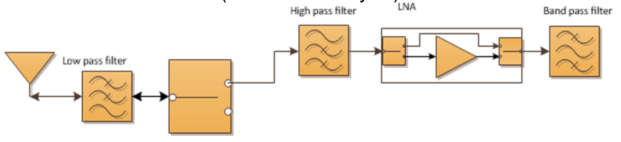
This above diagram is a basic representation of the radio, with correct filters in-place.
Let’s move onto the next “disturbance”. Side products or harmonics.
This is another effect that a WLAN Rx can receive from the nearby 3G/LTE stations.
For example, think about a 3G transmitter, which transmits ~1800Mhz (this is, lower frequency, hence F1 here) and ~2100Mhz (this is F2) at the same time. So, they produce harmonics and we can find this with 2xF2-F1 formula, which is (2 x 2100) – 1800 = 2400Mhz (Bingo!)
So, this is common problem for 3G operators using those frequencies together withing the same Tx chains.
This harmonics interference can be detected with an external spectrum analyzer:

Also, if the APs are spectrum analysis capable, they can also see this interference:

Swept spectrogram output of this harmonics is like below:
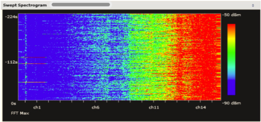
So, these interference does mainly affect 2.4Ghz band and less likely has an effect on 5Ghz band.
To mitigate these types of effects, mainly “high-power nearby signal” effect, it is better to use “filtered” APs at required locations.
